Keypad
📅 29. 2. 2024
Connecting a matrix keypad to the receiver. Characters are displayed on an LCD and sent via USB. While typing, you can switch between uppercase and lowercase letters and numbers. The device supports character deletion.
This project is available on GitHub:
Motivation
We’ve probably all seen a stenographic machine at least in American movies, a device utilized by court reporters for maximum efficiency. However, modern computer users are bound to a 60 to 100% keyboard, where fingers fly around quite a bit.
It wasn’t always like this. Once upon a time, there were keypad phones, and people were able to cover almost all of their buttons with only ten fingers. Thinking further: the keyboard has dimensions of 4x3, the left button with the right one on the bottom row are rarely used, so we have 10 buttons that we really need. And we can cover them with our fingers! Even a stenographic machine can’t do that!
The goal of this project is to go back a few years and kick-start a revolution in fast typing using components that have a price of only a few beers.
Features
- displaying typed characters on the LCD and sending them via USB
- the last two lines of text are shown on the LCD
- characters are sent via USB one by one
- when pressed repeatedly, the currently selected letter is displayed at the cursor position
- customizable key mapping (in the source code)
- customizable macro functions for the
A,B,C,Dbuttons, default configurations are as follows: - toggling between uppercase and lowercase letters and numbers
- uppercase/lowercase toggled with
A - numbers toggled with
B - when transitioning from uppercase letters to numbers and back, uppercase letters are maintained
- uppercase/lowercase toggled with
- scrolling on the LCD
- scrolling on the display is possible using
C - scrolling does not affect the transmitted data and is not equivalent to
\n; it is purely visual
- scrolling on the display is possible using
- deleting characters using
D - the LED lights up while any key is being pressed
Technical specs
List of components:
- Arduino UNO board with Atmega328P - the core of the device, communicates with outer devices via USB
- matrix keypad - used for device control
- LCD HD44780 16x2 - displays the text written by the user
- I2C converter for LCD - ensures communication conversion between the board and the LCD
Diagram
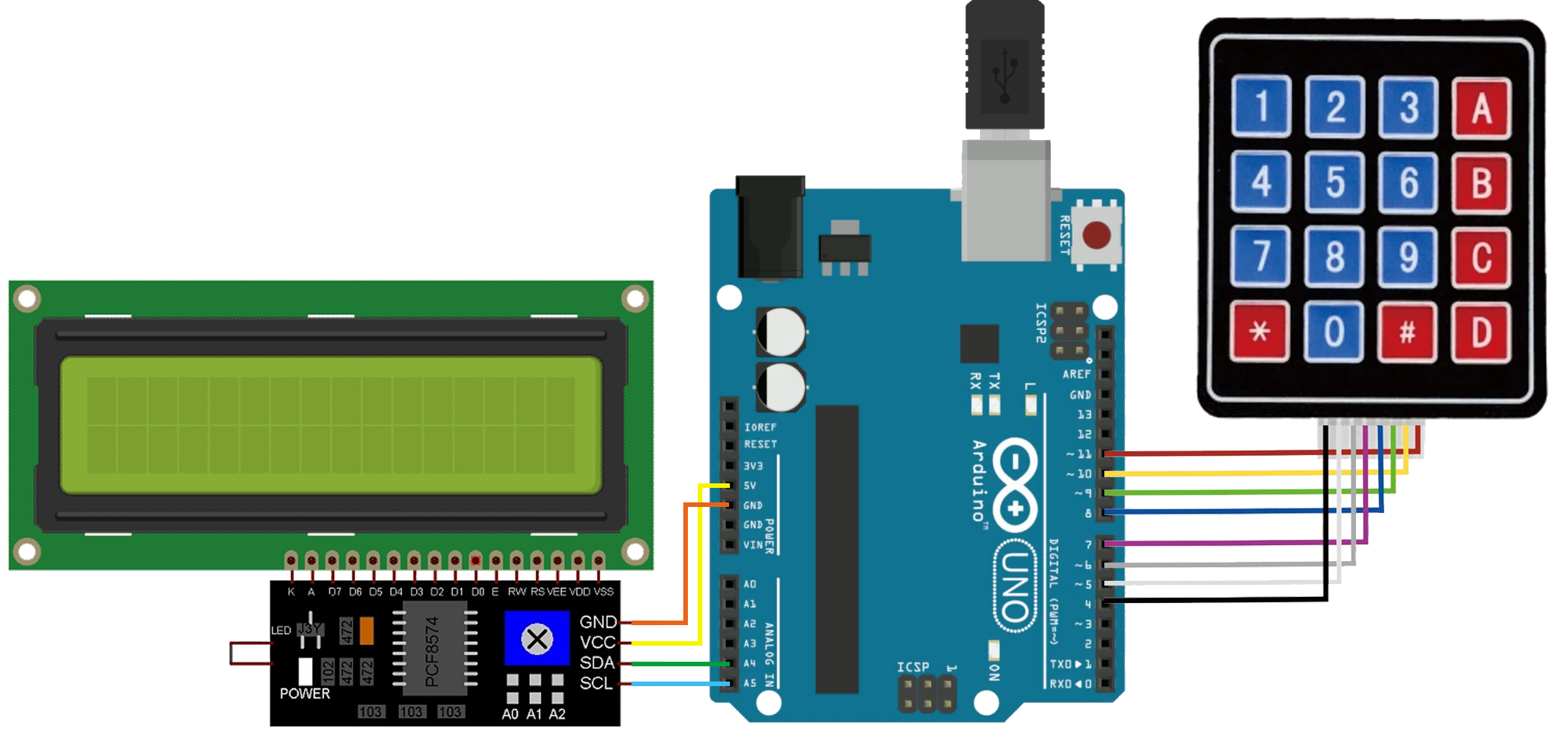
The LCD with the I2C converter is connected according to the diagram. The converter is then linked to the Arduino UNO through the A4, A5, 5V, and GND pins. The keypad is connected to pins 4-11, mainly for easier handling of the read results: pins 4-7 correspond to columns, while 8-11 correspond to rows.

Keypad
keypad.h
It handles reading from the keypad, decoding 8-bit numbers into matrix coordinates, and stores the data in the Key{row, column} structure. It provides other components with information about which buttons were pressed and how many times. It keeps track of the current mode, whether it’s in lowerCase, upperCase, numbers, and returns character values accordingly when queried.
Challenges
Keyboard Wiring: It is possible to connect the keypad to different pins than those specified above. However, caution is necessary: pins 0 and 1 (RX and TX) are not standard and cannot be used in this case. In case you want to change the wiring, minor adjustments in the Scan() function are needed. The orientation of the pins in relation to each other is crucial; if the output from scanning appears oddly rotated, the pins are likely rotated as well.
Scan Delay: A delay is incorporated in the scanning function. The registers require some time for changes written into them to take effect. The insertion of the nop function did not help; eventually, I settled for a delay of 10\(\mu \text{s}\).
LCD
lcd.h, HD44780_PCF8574.h
Displays characters written by the user. Manages basic functions such as scrolling and deletion. If the first line is filled, the text automatically scrolls to the second line. Upon filling the second line, it moves it up to the first, clears the second line, freeing space for further input.
Scrolling
It occurs either automatically after sending \n or after a line overflow or upon user request using the macro button. Shifts on the LCD are only sent to the receiver in the case of a newline character; all other scrolling is purely visual.
If the user scrolls in a way that the first line would be empty, the cursor moves to it to utilize the entire space on LCD.
Utilization of empty space:
+---------------------------+  y
| ABCDEF...                 |  0
| GHIJKL... _               |  1
+---------------------------+

*scroll*, *scroll*

+---------------------------+  y
| _                         |  0
|                           |  1
+---------------------------+
Maximum Deletion Length
Due to the technical implementation of the LCD class, it is only possible to delete characters in the currently active row - once a character has been “scrolled off,” it cannot be deleted from the LCD. However, commands for deletion can be sent via USB as many times as desired. If CAP_DEL_DISPLAY_SIZE == true in the config.h file, the number of deletions via USB is limited by the number of deletable characters on the LCD.
+---------------------------+  y
| ...                       |  0
| ABCDEF _                  |  1
+---------------------------+
The image currently displays 6 deletable characters.
Communication with LCD
The communication between the microcontroller and LCD via I2C is managed by the library HD44780_PCF8574 by Matiasus. My own implementation of necessary functions is built on top of this library in the LCD class.
Timer
timer.h
A timer in milliseconds from which the main program knows the time between individual key presses. It runs on TIMER0, and it’s not challenging to adapt it to other timers on the microcontroller.
The timer library is available on GitHub.
Main Program
main.cpp, config.h
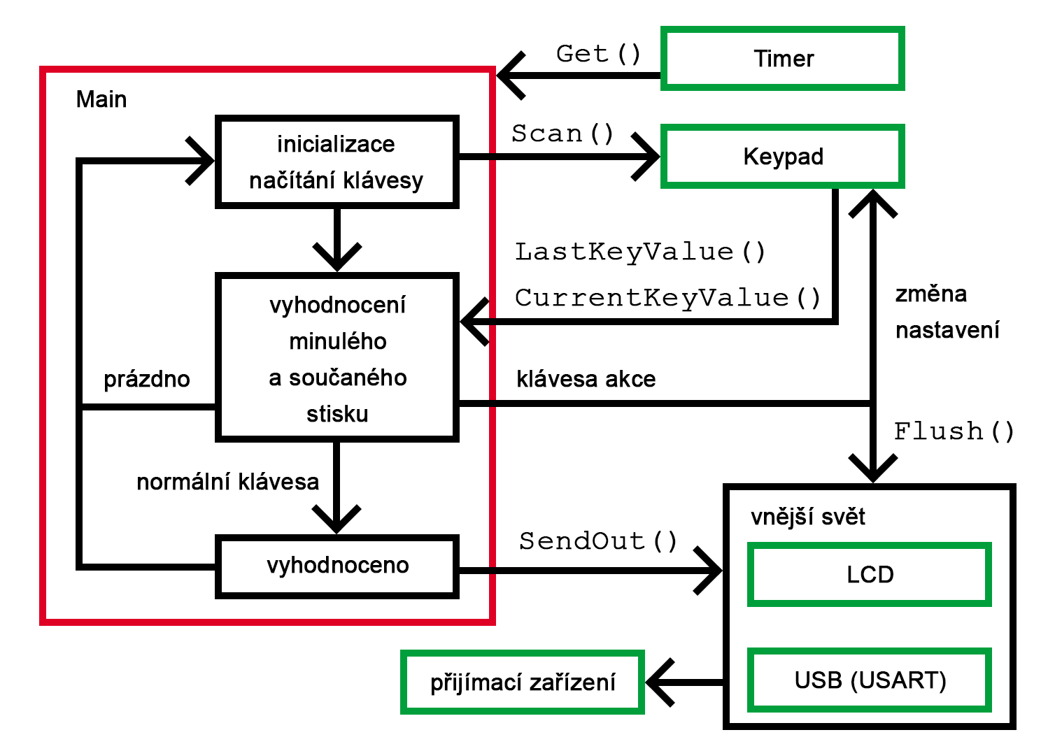
1) Retrieving a New Keypress
At the beginning of the main loop, the program reads the pressed key. It then checks if the press is valid (if any key was pressed) and notes that the keyboard is active. If nothing is pressed, it retries detect a keypress.
2) Evaluating the Keypress
The program checks if the pressed key corresponds to any action key. If yes, it adjusts the settings of individual classes to match the new requirements. If not, it continues with further evaluation. The main program obtains all information about keys using the functions LastKeyValue() and CurrentKeyValue(), which it calls from the keyboard.
The keyboard is responsible for correctly processing the button identifier, whether it is in any mode (lowerCase, upperCase, numbers).
3) Writing a Character
Writing of a character can occur for several reasons:
- the
PRESS_DELAYtime set inconfig.hhas elapsed, after which the device no longer waits and sends out the character - the pressed key contains only one symbol (in the default configuration, it could be the
#key, mapped to the\ncharacter), there is no need to wait to see if the user selects a different character from the key, as no other character is associated with it - another key is pressed, the program has to handle this new key, and the last selected character is displayed
- a macro is triggered, requiring a transition to new settings, and the last selected character is displayed
Transitions between these states are managed by the Flush() function.
After this step, the entire cycle repeats.
Main loop sketch

Possible Improvements
- More keyboard modes and improved indication (e.g., using multiple differently colored LEDs).
- On-the-fly key mapping configuration. Entering a menu where the user can click to choose which letters they want on the keys.
- On/Off button.
- Placing the device in a compact enclosure, approximately 9x12 cm.
- Bluetooth, Wi-Fi connectivity to the computer, enabling text input from virtually anywhere.
- Linking with a PC to use the device as a full-fledged keyboard. Currently, I only display its output in a terminal monitoring the serial link.
- Mouse cursor control mode. The keypad has enough buttons for it, and we could even support diagonal movement.
License
I am not a lawyer, but! without any warranty:
The entire project is under GPL3 due to the use of the library for controlling the LCD. Consider the rest of the project as libraries I wrote myself, and they are available under the MIT license. If anyone happens to do something cool with it, let me know. Thanks.
